

What is a Silica Fume Material Pneumatic Conveying Machine? And What Are Its Design Principles?
For industrial applications that require the efficient and reliable transport of silica fume—a fine powder commonly used in concrete production and other construction materials—pneumatic conveying systems offer a sophisticated solution. A silica fume material pneumatic conveying machine is a specialized piece of equipment designed to move this lightweight, high-density powder through a pipeline using compressed air or other gas. This method of material handling is particularly advantageous for applications where traditional methods like belt conveyors or bucket elevators may be less effective due to the material's characteristics, such as dustiness, hygroscopicity, or the need for contamination-free transport.
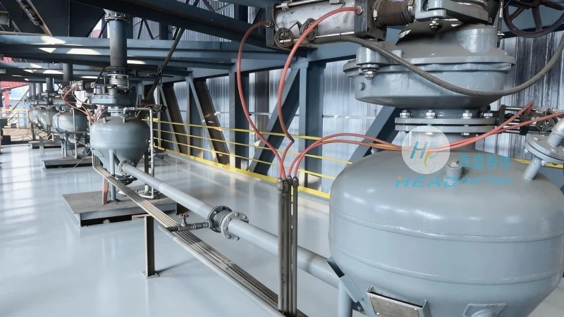
The core function of such a machine is to take silica fume from a storage silo or hopper and deliver it to a processing unit, such as a mixer or a storage tank, with minimal loss and maximum efficiency. The design of these systems is critical to ensuring optimal performance, as the properties of silica fume—like its fine particle size, which can cause clogging or increased friction—must be carefully considered in the engineering process.
Design Principles of Silica Fume Material Pneumatic Conveying Machines
The design of a silica fume material pneumatic conveying machine is guided by several key principles to ensure it can handle the unique challenges of transporting this material. First, the system must be capable of generating sufficient air velocity to keep the powder suspended in the air stream. This is typically achieved through the use of high-pressure blowers or compressors that can maintain a consistent airflow rate. The air velocity must be high enough to overcome the gravitational forces acting on the silica fume particles but not so high as to cause excessive wear on the system components or generate excessive noise.
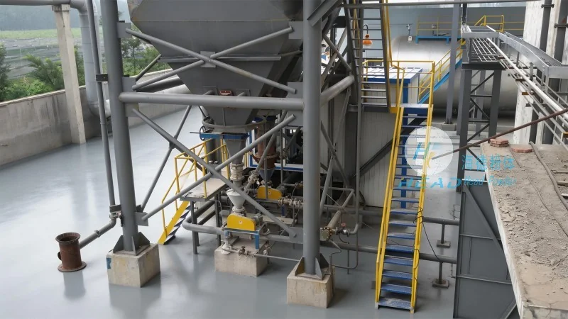
Second, the design must address the issue of particle size and flowability. Silica fume particles are extremely fine, often ranging from 0.1 to 1 micron, which can lead to clogging in the pipeline if the system is not properly designed. To mitigate this, the conveying system may incorporate features like pulse-jet cleaning, where short bursts of high-pressure air are used to dislodge any particles that have settled on the pipe walls. Additionally, the use of smooth, corrosion-resistant materials for the pipeline—such as stainless steel or PTFE-coated tubing—is essential to prevent particle accumulation and ensure consistent flow.
Third, the system must be designed to minimize pressure drop and energy consumption. The pressure drop in a pneumatic conveying line is a critical factor, as it directly impacts the amount of energy required to move the material. Engineers use computational fluid dynamics (CFD) and other simulation tools to optimize the pipeline layout, including the use of bends, elbows, and expansion joints, to reduce friction losses. This optimization ensures that the system operates efficiently while maintaining the required air velocity to keep the silica fume suspended.
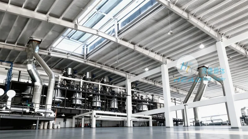
Components and Operation of the Pneumatic Conveying System
A typical silica fume material pneumatic conveying machine consists of several key components that work together to achieve the desired transport. The main components include a material feed hopper, a rotary airlock valve (also known as a feeder), a pipeline system, a pressure vessel or receiver, and a control system. The feed hopper is used to store the silica fume and provide a consistent feed to the system. The rotary airlock valve is a critical component that prevents the backflow of air into the hopper and ensures a steady flow of material into the pipeline.
The pipeline system is the heart of the conveying process, and it is designed to handle the high velocity air and fine particles. The pipeline is usually made of stainless steel or other corrosion-resistant materials to prevent the silica fume from adhering to the walls. The system may include various fittings, such as elbows, tees, and reducers, to direct the flow and change the direction of the material. The pressure vessel or receiver is used to collect the silica fume at the end of the pipeline and can be equipped with a discharge valve to control the release of the material.